
Mixed Part Sizes Causing Uneven Plasma Polishing? A Scenario-Based Fix
A finishing line that runs small precision components alongside larger machined housings in the same plasma polishing cycle rarely achieves uniform results across the entire load. Small parts may come out over-polished, with edge rounding or surface etching that exceeds specification. Larger parts may still show residual burrs or incomplete surface refinement. The usual response is to adjust the electrolyte, change the cycle time, or blame the equipment. In many cases, the root cause is a mismatch among three variables that must be aligned before the process can be stable: part geometry, batch yield, and machine configuration.
This article takes a scenario-based approach to that problem. It explains how to diagnose whether mixed part sizes are the actual driver of uneven results, how to map the application to the standard 100A–800A plasma polishing model range or to non-standard 1000A–2500A equipment, and how Dongguan Bayi Automation Equipment Co., Ltd. (brand: Bayi) approaches customization when standard configurations do not fit the production mix. It closes with a practical intake checklist that buyers can use before requesting a configuration from any plasma polishing machine supplier.
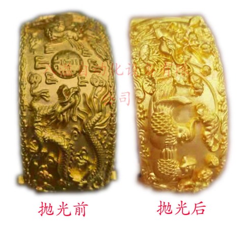
Mixed part geometries create different surface-area and current-demand profiles within one plasma polishing cycle.
What Uneven Plasma Polishing Actually Looks Like
Uneven results in a mixed-size batch tend to appear in one of three patterns. Recognizing the pattern narrows the diagnostic path.
Batch-to-batch variation. The same parts, run through the same cycle recipe, produce different surface finishes from one load to the next. This pattern usually points to variation in rack loading, part spacing, or contact resistance rather than to a machine fault. If the operator loads the rack differently or changes part orientation between cycles, the current distribution across the workload changes accordingly.
Within-batch variation. Parts in one load show different finishes depending on their position on the rack or their size relative to neighboring parts. Small parts near the current-carrying contacts may polish more aggressively than large parts at the outer edge of the rack. This pattern points to current-density imbalance across the load and is the most common signature of mixed-size processing.
Geometry-specific underperformance. One family of parts consistently under-polishes regardless of where it sits on the rack, while other geometries in the same batch finish correctly. This pattern suggests that the process window — current, time, electrolyte concentration, and temperature — was established for a different geometry and does not transfer to the part family that underperforms.
Distinguishing under-polishing from over-polishing matters. Under-polishing leaves burrs, surface roughness above target, or visible machining marks. Over-polishing manifests as edge rounding beyond tolerance, dimensional change on thin features, or a surface that appears etched or pitted. A batch can contain both conditions simultaneously when the part mix spans a wide size range.
Why Mixed Geometry Challenges a Single Process Window
Plasma polishing is a surface finishing process that combines electrochemical and plasma effects to clean, polish, and deburr metal workpieces. The part is immersed in an electrolyte and subjected to an electrical current; the resulting plasma discharge at the part surface removes material, smooths micro-irregularities, and can round edges. Because the process is electrically driven, the distribution of current across the workload directly affects how evenly material removal proceeds.
Three factors interact when parts of different sizes share a cycle.
Total exposed surface area
Current density — the current per unit of exposed surface area — influences the local polishing rate. A rack loaded with many small parts presents a different total surface area than a rack loaded with a few large parts. If the machine's current setting is optimized for one load profile, the other load profile will experience either insufficient or excessive current density. In a mixed load, both conditions can exist simultaneously on different parts.
Rack loading density and spacing
Parts positioned close together can shield one another from the current field. Small parts placed between larger parts may sit in a region of lower current density. Conversely, small parts at the outer edge of the rack may receive more current than intended. The physical arrangement of mixed geometries on the rack therefore changes the effective process conditions for each part, even when the machine settings remain constant.
Hanger space and working envelope
Every plasma polishing machine has a defined hanger space — the volume in which parts can be suspended for processing. The BY-100A model, for example, provides a hanger space of 360 × 260 × 200 mm. Parts that exceed this envelope cannot be processed in that model, and parts that are much smaller than the envelope may not use the available current efficiently. When a production mix includes parts near or beyond the hanger-space limit, the machine configuration itself becomes a constraint on batch composition.
Decision rule: Before adjusting process parameters, confirm that the part mix actually fits the machine's hanger space and that the total surface area per load falls within the current capacity of the model. If either condition fails, parameter tuning will not produce a stable result across the full mix.
Diagnosing the Mismatch: Geometry, Yield, or Machine Configuration?
A structured diagnostic sequence separates the three variables and prevents unnecessary parameter changes. The goal is to identify which variable is driving the variation before making adjustments.
Step 1: Document the part geometry
Record the dimensional range, shape category, and surface-area profile for every part in the mix. Group parts into geometry families — for example, small rotational parts, flat plates, and complex 3D-printed lattice structures. Note which families share a cycle and which are processed separately. If possible, measure or calculate the exposed surface area for a representative sample from each family. This record becomes the baseline for comparing process outcomes.
Step 2: Record the batch yield and rack pattern
For each cycle, document the number of parts per family, their positions on the rack, the spacing between adjacent parts, and the location of current-carrying contacts. Photograph the loaded rack before processing. If results vary between cycles that use the same part mix, compare the rack photographs to identify changes in loading pattern or part orientation.
Step 3: Compare outcomes against the machine configuration
Map the documented part mix against the machine's rated current, hanger space, and recommended load range. If the total surface area of a mixed load exceeds what the current setting can drive evenly, or if parts approach the hanger-space boundary, the configuration is a contributing factor. If the mix fits comfortably within the machine envelope and results still vary, the issue is more likely in rack loading or process-window transfer between geometries.
Diagnostic matrix
| Observable symptom | Likely variable | First diagnostic check |
|---|---|---|
| Small parts show edge rounding or etching; large parts retain burrs | Current-density imbalance across mixed surface areas | Compare total exposed surface area per rack load against the model's rated current |
| Results vary between cycles using the same part mix | Rack loading pattern or part orientation changed | Photograph and compare rack layout, part spacing, and contact points for each cycle |
| Parts near rack contacts polish differently from parts at the outer edge | Contact resistance or current shadowing | Inspect contact points for wear or poor contact; check spacing between adjacent parts |
| One geometry family consistently underperforms regardless of position | Process window set for a different geometry | Review current, time, and electrolyte parameters against the specific part family |
The matrix is a starting point, not a definitive diagnosis. Combinations of variables are common. For example, a rack that mixes small parts with large parts may show both current-density imbalance and contact-related variation. In that case, address the rack loading pattern first, then reassess whether the machine configuration can support the revised load.
Mapping the Application to Standard or Non-Standard Equipment
Once the diagnostic sequence identifies the variable driving uneven results, the next step is to determine whether the existing machine can be adjusted or whether a different configuration is required. Bayi organizes its plasma polishing machine range into standard models from 100A to 800A and non-standard models from 1000A to 2500A, with the specific configuration designed around the customer's product size, shape, and yield requirements.
Standard 100A–800A models
The standard range includes the 100A, 300A, 500A, and 800A models. The BY-100A model, for example, operates at 30 kW with a three-phase five-wire 380V input, a maximum output current of 100A, and a hanger space of 360 × 260 × 200 mm. As current capacity increases across the range, the machine's ability to drive larger total surface areas or higher part counts per cycle generally increases, but the specific working dimensions and throughput for each model should be confirmed against its current datasheet.
Standard models are appropriate when the part mix fits within the hanger space and the total surface area per load can be handled by the model's current capacity. For mixed-size production, a standard model can work if the rack loading pattern is designed to distribute current evenly across the mix — for example, by grouping parts of similar surface-area profile in consistent positions on the rack.
Non-standard 1000A–2500A equipment
Non-standard models from 1000A to 2500A are configured for applications that exceed the working envelope or current demand of the standard range. This includes parts that are too large for a standard hanger space, production volumes that require higher throughput per cycle, and part mixes that present a total surface area beyond what a standard model can drive evenly. The specific configuration — hanger dimensions, current capacity, automation level, and material handling — is designed around the customer's product size, shape, and yield requirements.
Bayi also produces customized special equipment outside the standard and non-standard model framework, including tape-type plasma polishing equipment for continuous processing of square material, long-tube plasma polishing equipment for pipes over 2 meters in length, and chain-type plasma polishing equipment for automatic collection and roll polishing. These configurations are relevant when the part geometry itself — not just the size mix — requires a non-standard material handling approach.
How Bayi Approaches Customization for Mixed-Size Production
Dongguan Bayi Automation Equipment Co., Ltd. was established in June 2017 and operates an 800 m² factory with 50 employees. The company's core technical team brings 17 years of plasma polishing and deburring equipment research, development, design, and manufacturing experience, supported by a 3-engineer R&D team. Bayi's standard models are 100A, 300A, 500A, and 800A, with non-standard models from 1000A to 2500A designed according to the customer's product size, shape, and yield requirements.
For mixed-size applications, the customization process starts with the part mix rather than with a pre-selected model. The relevant inputs are the dimensional range of the parts, their shape categories, the required surface finish, the production volume per shift, and the rack loading pattern. From those inputs, the configuration decision follows a practical sequence: confirm the hanger-space requirement, calculate the total surface area per intended load, match that surface area to the current capacity, and then specify the automation level and material handling that fit the production environment.
Bayi's production capability includes a monthly capacity of 70,000–110,000 units for medium parts, a lead time of 30–45 days, and a minimum order quantity of 1 unit. Quality control is 100% test. The company exports to North America, Europe, and Southeast Asia, and provides remote support for after-sales service. A documented application example is Hebei Hengxin, which operates two Bayi units for electronic accessory processing and reports stable operation over seven years, with installation guidance provided by Bayi.
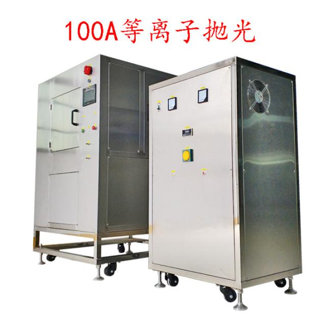
The BY-100A plasma polishing machine provides a defined hanger space that constrains the part mix it can process in one cycle.
Intake Checklist Before Requesting a Configuration
A complete intake record shortens the configuration review and reduces the risk of specifying a machine that does not fit the actual production mix. The checklist below covers the information a plasma polishing machine supplier needs to evaluate a mixed-size application.
- Part dimensional range: Minimum and maximum length, width, height, and diameter for every part family in the mix.
- Shape categories: Rotational, flat, complex 3D-printed, tubular, or irregular; include drawings or photographs of representative parts.
- Material: Stainless steel, titanium, titanium alloy, or other conductive metal; note any material combinations within one batch.
- Surface finish requirement: Target roughness or visual standard for each part family; identify whether the requirement differs across the mix.
- Production volume: Parts per shift, parts per cycle, and the expected batch frequency for each part family.
- Rack loading pattern: Current rack dimensions, number of positions, spacing between parts, and contact method; photographs of a loaded rack are helpful.
- Existing process data: Current machine model, cycle time, current setting, electrolyte type, and any documented results from previous trials.
- Environmental and handling requirements: Available floor space, power supply, air supply, and any need for dusting and fume extraction or workpiece handling and positioning systems.
- Quality acceptance criteria: How the buyer will judge whether a processed part meets specification — visual inspection, roughness measurement, or functional test.
The checklist is not a substitute for sample processing. It organizes the information that makes sample processing meaningful, because the supplier can design the trial around the actual part mix rather than around a single representative part.
Application Scenarios Where Mixed-Size Processing Matters
Mixed-size plasma polishing appears across several manufacturing contexts. The common thread is a production environment where variety is inherent and dedicating a separate machine to every part family is impractical.
3D printing post-processing. Additive manufacturing produces parts with varied geometries, including lattice structures, small dental components, and larger industrial prototypes. The application context for 3D printing plasma burring equipment specifies polishing and deburring treatment, with operation that can be set automatically at regular intervals, and requires use with a dusting and fume extraction system and a workpiece handling and positioning system. The process is suitable for applications in the 3D printing sector, where mixed part sizes are normal.
Medical device components. Precision deburring and ultra-fine polishing are relevant to medical device manufacturing, where small instruments and larger housings may share a finishing department. The BY-800A model, for example, is a titanium plasma polishing machine with a stated deburring rate of ≥99.9%, a fully automatic control system, and application scope that includes medical care, confidential processing, 3D printed dentures, and precious metal and gold jewelry.
Jewelry and precious metal finishing. The BY-500A model is a jewelry plasma polishing machine designed for stainless steel jewelry applications, with precision deburring and ultra-fine polishing functions. Jewelry production often mixes small rings, clasps, and larger decorative pieces in one finishing cycle.
Precision hardware and electronics. The Hebei Hengxin case describes two Bayi units used for electronic accessory processing over seven years of stable operation. Electronic accessory production typically involves small parts with tight dimensional tolerances, where over-polishing is as much a concern as under-polishing.
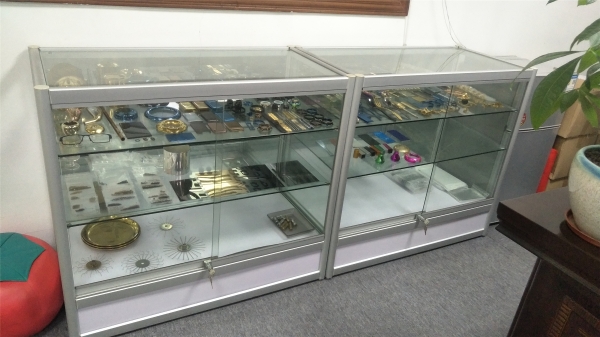
A processing sample display shows the range of part geometries and materials that plasma polishing equipment is configured to handle.
Frequently Asked Questions
What are the first signs that mixed part sizes are causing uneven plasma polishing?
The most common first sign is within-batch variation: small parts near the rack contacts show edge rounding or etching while larger parts at the outer edge retain burrs. A second sign is batch-to-batch variation when the part mix stays the same but the rack loading pattern changes. A third sign is one geometry family consistently underperforming regardless of its position on the rack, which points to a process window that was set for a different geometry.
Can one plasma polishing machine process both small and large parts without uneven results?
Yes, within limits. A single machine can process mixed sizes if the total surface area per load fits the model's current capacity and every part fits the hanger space. The BY-100A, for example, provides a hanger space of 360 × 260 × 200 mm with a maximum output current of 100A. When the mix exceeds either the hanger space or the current capacity, a standard model may not deliver even results across the full load, and a non-standard configuration from 1000A to 2500A becomes relevant.
When should I choose a standard 100A–800A model instead of non-standard 1000A–2500A equipment?
Choose a standard model when the part mix fits the hanger space and the total surface area per load can be driven evenly by the model's current capacity. Choose a non-standard model when parts exceed the standard hanger space, when production volume requires higher throughput per cycle, or when the combined surface area of the mix exceeds what a standard model can process uniformly. The specific decision depends on the documented part dimensions, shape categories, and yield requirements.
What information should I prepare before requesting a custom configuration?
Prepare the part dimensional range, shape categories, material, surface finish requirement, production volume per shift, existing rack loading pattern, current process data, available floor space and utilities, and quality acceptance criteria. Photographs or drawings of representative parts and a loaded rack are particularly useful because they let the supplier evaluate the actual geometry mix rather than a single sample part.
What are Bayi's lead time and minimum order quantity for a custom configuration?
Bayi's lead time is 30–45 days and the minimum order quantity is 1 unit. Monthly capacity for medium parts is 70,000–110,000 units, and quality control is 100% test. Buyers can request a configuration review or submit sample parts for evaluation by contacting Bayi through its official website or downloading the company brochure for detailed capability information.
Conclusion
Uneven plasma polishing in a mixed-size batch is usually a configuration problem, not a machine failure. The diagnostic sequence — document the geometry, record the batch yield and rack pattern, then compare against the machine's current capacity and hanger space — separates the three variables and points to a practical fix. Standard 100A–800A models suit part mixes that fit within their working envelope. Non-standard 1000A–2500A equipment, configured around product size, shape, and yield requirements, extends the range for mixes that exceed those limits. The intake checklist in this article gives buyers a structured starting point for the configuration conversation, and Bayi's 17 years of core technical experience and 3-engineer R&D team provide the application knowledge to translate that checklist into a working machine specification.
For buyers who want to review Bayi's full product and capability documentation, the company brochure is available for download: Bayi Automation Company Brochure.
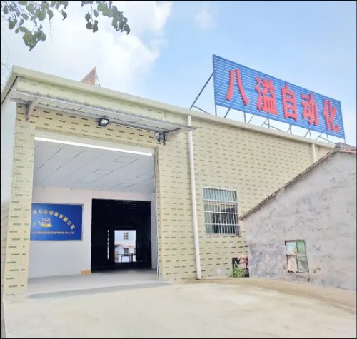
Bayi's 800 m² production facility in Dongguan supports standard and customized plasma polishing machine configurations.
Have Questions or Need More Details?
Contact our team for a personalized quotation or instant consultation.
Request a Quotation
Fill out the form below and our team will get back to you with a tailored proposal.
WhatsApp Direct Chat
Prefer to chat in real-time? Message us on WhatsApp for instant assistance & quick answers.
- Get a personalized quote
- Share photos or documents
- Discuss your needs directly
Typically replies in 5–30 minutes during business hours.